Morsiani Radar

Multifunction- Radar Detector
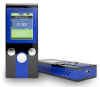
The Morsiani Radar is the latest generation of digital metal detectors. It is embedded in a PC-System and has a 640x480 Pixel extreme clear touch screen colour display. GPS is integrated for mapping data from the search area.

Morsiani Radar can directly display a 3D live scan image of the detection area and save the data for later reference in the unit.
Morsiani Radar can work as a pulse induction detector with discrimination or as a magno-radar with the magnetometer coil with 8 sensor / 2 Axis double sensitivity
In this configuration the Morsiani Radar combines two different search detector systems for different search applications. The detection analysis works for the both systems at the same time.
Currently, the ProGeo software can only display one detection analysis at one time. An extended software version which can display both systems at one time is on under development.


Likewise under development is a active and a passive VLF-Groundradar antenna as well as a HF-Ground radar coil. The HF-Coil is a PULSE-Radar which can detect caves and give information about the depth of the objects.

The final software version will combine several detection systems in one unit. The Morsiani Radar records the search data automatically.
If required you can further analyze the data on a PC with a higher resolution with the 3D-Software ProGeo.
Of course you can as well analyze the images with the Morsiani Radar on location.
For these purposes, you can use the internal keyboard or an external Keyboard with mouse.
With the Morsiani Radar you obtain a detector for all detection alternatives. Morsiani Radar - a detector for the future.

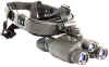
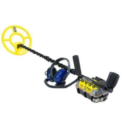
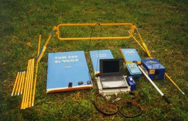
Morsiani Radar Basic Elements
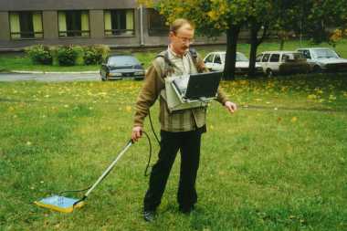
1. Detector with carrying belt.
2. Aluminum-Carrying case
3. Stereo Headphones with cable and adjustable volume
4. 2x rechargeable batteries NiMH 21.6V/3Ah with 2x Charger
5. Telescope bars
6. 28cm Coil
7. Mini-Keyboard
8. USB Stick
9. Touch-stick
Operating time with one battery at pulse power 1 - about 3 hours. In the magno- or vlf modus - about 4 hours. If you plug two batteries, you have twice the operating time.
General Information
The detector works with Windows XP-Embedded. The system is consisting of minimum configuration.
If the detector does not boot directly, please turn it off and on again. This can happen due to the static of the electrical pulse condensers which can lead to voltage drops.
To turn the detector off, please follow these steps:
- Turn off the Morsiani Radar desktop via the Key EXIT in the . The Start menu appears.
- Click on Exit Windows and after 8-10 seconds the Windows logo appears.
- Turn off the Power switch on the left side on the unit.
If you turn off the unit directly, booting will take a little longer when you start the system again as the file system has to be corrected.
Please note that the battery display will only be active if you turn on the START RX button. If the START RX button is turned off and the display is flashing, please turn off the unit immediately.
If the data transfer between PC-Board and detector-board is faulty, push the switch over the USB port.
With this switch you restart the detector-board without turning off the detector.
This can happen if you unplug the MagnoRadar or the Coil while working, since the data transfer is being disconnect.
Dont do this. Never disconnect coil by working. Only if you get a message for disconnect coil.
In the Menu DETECTORS you can stop all working detectorsystems by the button RESET DETECTORS.
Starting Display

After the booting the following system desktop appears.
From this desktop you can manage all basic operations. This desktop is also prepared for the following upgrades in the future.
Function:
Morsiani Radar : With this button you start the detector. Explorer: With this button you start Windows Explorer. Notepad: With this button you start the editor for your notes. Keyboard: With this button you start the onscreen keyboard.
Thus you can make notes without an external keyboard or mouse, in the field (for instance an interesting detection file).
With the button COPY you can copy the whole data register (C:\Datafiles), which contains all log-data, to a USB Stick. Plug the USB stick into the USB port an wait 8-10 seconds until the stick is connected to the system. Now click to button COPY.
With the button TOUCH you can adjust the touch screen. Adjust the touch only if it does not work properly. This normally happens after 1-2 years.
With the button EXIT WINDOWS you can turn the system off. Please wait 8-10 seconds until the windows logo appears
After starting Morsiani Radar, the 3D Real Plot display will be appear.
After starting Morsiani Radar, the 3D Real Plot display will be appear.
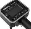
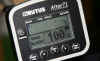
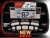
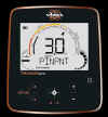
Morsiani Radar Operating Display

This is the operating display for detection.
The detection signals is shown on a numerical scales and a bargraph in real time 3-D graphic.
Red is the All-metal signals, blue is the ferrous and yellow is the non-ferrous signal.
That applies to the numerical display and for the bar-graph. The green scale shows the state of rechargeable battery in %.
In the Magno operating modus the red color is the minimum value and the yellow color the maximum value of the detection signal.
The blue color expresses the difference of the left and right side of the coil.
You can use the touch pads with your fingertips or the touch pen.
IMPORTANT!!

If you turn of the Morsiani Radar desktop via the EXIT button. And if you want to start again the Detectorboard than you have to
push the reset button over the usb port for remove the detector board.
The operating functions of the 3D Real Plot display START RX:
This button starts the connection to the detector board. The detection signals
are transmitted to the program.
Please note that the battery scale is active only if you turn on the button START RX.
Some functions automatically turn off the START RX button. Those are explained later in this manual.
STOP RX:
This button stops the connection to the detector board.
LOGGING:
With this button you activate the recording of the detection signal. The maximum recording is 6400 signals. The size of the real-time plot consists of 80 x 80 segments of points and is stored every time the maximum is reached. The stored files are called: PULSDATxxx.asc or MAGNODATAxxx.asc. The xxx after the name starts with 100 and is increase by one (for example: 101,102,103 etc.) The files will be stored in the folder C:\Antares\Datafiles with the latest file shown on the top of the folder.
The recording is activated with the button GO. The RX DATA scale displays the counted datasets. With the button GO and STOP you can control the recording. The recording will automaticly save is the plot is full.
With button SAVE LOG you can also directly save the data or a part of the data. This will only work if the GO button is active.
MOTION:
With the Up/Down buttons you select the recording speed of the 3D Plots and the size of the area you want to see on the graphic plot. Lower speed for bigger area and higher speed for small area. The motion value (recording speed) defines the number of measures on a line that are averaged to one value. Thus, an increased motion value allows you to walk a longer line (with the same accuracy) or gives you a more accurate measurement of the same line.
For example, at motion value 1 you measure 80 points ( i.e. one point per meter on an 80 meter line). At motion value 2, you can measure the same line (80 meters) with 160 points, thus getting double accuracy. Or else, you walk a 160 meter line with the same accuracy (you line is getting twice as long etc.).
The real-time signal of the scales and bar graphs is not being effected. Only the plot speed gets slower/faster.
Exit:
With the EXIT button Detectorsystem will close.
GO:
With this button you start the 3D Plot.
STOP:
With this button you stop the recording of the 3D Plot.
SAVE LOG:
With this button you can save every time the results of the 3D Plot. By the 3D recording the GO button has to be on. The Logging doesnt have to be activated. You dont have to be wait until the 3D plot completely full. The plot would not be delete and can go on.
SAVE LOG:
With this button you can directly save the plot or a part of the plot at every time. But the GO button must activated.
CLEAR:
With this button you can delete the 3D Plot. START RX goes on STOP RX and one activated recording goes on STOP.
AUDIO:
With this up/down button you adjust the threshold of the tone. The higher you choose the value the smaller the signal strength of a measured object may be.
Generally a click rate of 1-2 will be adjusted without signal.
GROUNDCAL:
With this button you activate the automatically ground balance. This automatic balancing is still on development and works not so secure.
REFERENCE:
With this feature you calibrate the detector. All actual detection signals thermal deviations gets to a zero value. By pressing the pushbutton REFERENCE the memories are loaded new with the searchsignals at this time. Now this is the new Reference signal for the new search. All driftings will be compensated. If you do a REFERENCE above a metal object, this object also will be compensated and can not be detected any more.
ANGLE Z:
You can turn the plot
ANGLE X:
You can tip the Plot.
ZOOM:
You can zoom the graphic
Z SCALE:
For a better view you can change the height of the data cell on the graphic.
CURSOR:
If you move the mouse over the graphic the data cells will be signed.
MESH:
You can close the grit. Especially by a resolution of 100 the colours are out of recognition
The operating display of Pulse Menu

The operating display of Pulse Menu
On the pulse menu display you can change the parameters and call up different functions. If you change to this display the recording 3D Real plot turns off. Go jumps to STOP. You have to push the button GO if you return to the 3D Real plot. On this Display you can see again the numeral values, bargraph and the detection spectrum. Therewith you can see immediately all the changes you did. So you can change your detection features on this display. You can also seach with this display.
FERRO:
With this button you activate the FERRO- and the all metal signals on the 3D Real Plot. So all the detecting signals will be shown and recorded. If you activated the logging button than you can see later both scan (ferrous or non- ferrous) on this modus. With or without ferrous signals will be stored.
NONFERRO:
With this button you activate the precious metal signals on the 3D Real Plot. So it will shown only the precious metal signals on the graphic. If you activated the Logging button than you can see later both scan (ferrous or non-ferrous) on this modus. With or without ferrous signals will be stored.
If you save a plot with LOGGING or SAVE LOG all datas will save. There are no data lost if you change Ferro/Nonferro.
CHANGE COIL:
Here you advise to the software that you want to change the coil. The pulseshut down and it appears a little menu display. After you changed the coil you have to click on RESTART. The pulse starts again. It takes 30-40 seconds until the detector is ready. This function is only active if the START RX is turned on.
STOP PULSE:
Here you turn off the pulse signals. If you connect the
MagnoRadarCoil and you want to disconnect the PI-Coil from the unit. Or you want to dig and dont want to turn off the unit. You save power. This function is only active if the START RX is turned on.
RESET GROUNDCAL:
With this button you can reset to the factory default value of ground balance.
This function is only active if the START RX is turned on.
CHANGE VALUE:
After changing the following parameter values you have to activate the adjustment with this button. This function is only active if the START RX is turned on.
PULSE POWER:
With this button you change the power of the pulse signals. Please note: If you increase the pulse power also the power requirement increase equal. This parameter adjustment has to be activate with the CHANGE VALUE.
A pulse power changing needs a few seconds until the system stabilized again. So you have to make REFERENCE 2-3 times. FREQUENCY:
The detector own three different pulse frequencies:
1=480Hz; 2=320Hz; 3=100Hz. As lower the frequency as better the penetrating in the mineralized ground. Because the frequency of 100 Hz has a quarter of data rate from 480 so the discrimination feature changes also. The parameter has to be activated with CHANGE VALUE.
GAIN DECREMENT:
Here you can change the sensitivity. The sensitivity will be reduce accordingly to the numeral value. Two means the sensitivity getting halve etc. This changing will be done immediately.
GAIN INCREMENT:
Her you can change the sensitivity. The sensitivity will be increase accordingly to the numeral value. Two means the sensitivity getting doubled etc. This changing will be done immediately.
DISCRIMINATOR:
Here you can change the sensitivity of the discriminator. The higher the value the bigger the ferrous sensitivity. This changing will be done immediately.
OBJECT:
With this button you can adjust the sensitivity to the small objects. The bigger the coil and the bigger detection depth you want the bigger the adjustment value. So you have to overlook the summery of all objects in higher formations. So with this adjustment you can also discriminate the small object trash over the ground. This parameter has to activate with CHANGE VALUE.
The operating display of Magno Menu

On the MAGNO MENU display you can change the parameters and call up different functions. If you change to this display the recording 3D Real plot turns off. Go jumps to STOP. You have to push the button GO if you return to the 3D Real plot. On this operating display you can see detection values of the eight mango coil sensors and the value difference between the left and right sight side of the coil. As well there is a spectrum of the MagnoRadarCoil. The yellow bar graph shows the difference value from the left and right side of the coil. Consequently the you can recognize all changes under the coil. So from this display you can adjust your detection features and certainly effect a real-time scan.
RESOLUTION:
Here you can adjust the sensitivity of the sensor in 8 levels. The maximum sensitivity of 10nTesla is level 1. Normally you must set RESOLUTION to a lower sensitivity because 10nTesla is very sensitive.
AUDIO GAIN:
Because the operating range of the audio generator is smaller than the rejection of the detecting signals so you can decrease the sensitivity of the tone generator. The tone generator react only the difference signal reaction to the left and right side of the coil. It gives you only reaction if a metal detected between the left or right side of the coil.
MAGNO GAIN:
Here you can increase the sensitivity of the sensors. Please note: If you
decrease the resolution and increase mango gain thats certainly absurd.
The operating display of Data Input

On the Data Input display you can load the stored files.
Load Data:
With this button you open the files menu. Now you can load the logged data files. Please take care that the program is on the right modus. If you are on the pulse modus you can load only the pulse scans well only Pulsdataxxx.asc files. If you are on the magno modus you can load only the magno scans well only Magnodataxxx.asc files or if you are in Vlfmodus only Vlfdataxxx.asc.
SHOW 3D DATA PLOT:
The loaded scan will shown on the 3D Data Plot display. Cause the data amount are composed of 80 x 80 x22 data records so it can take about 40 second until you get a picture.
SHOW 3D REAL PLOT:
The loaded scan will shown on the 3D Real Plot display. After some second the picture switch to Real3DPlot an you see the search in same way you have saved..
SHOW 3D All Plot:
The related calculation of Pulse,Magno and Vlf records are on the developing.
You can also copy the data files to you USB-Stick and look on you PC with the ProGeo Demo-software in high resolution. To copy complete data records please look at page 5 or you can copy single data files.
You find the data files on C:\ANTARES\datafiles
- plug the USB stick in the USB port
- Close the ANTARES display
- open the explorer, go to the file C:\ANTAREs\datafiles , choose and click on the file you want to copy to the USB-Stick and shifted to the folder D:\Datafiles
operating display of the Vlf Menu

With the VLF Menu you can change and set the parameter for the Vlf sensor. This menu also show the signals. There are also the parameter for the Vlf sensor with 3axis Magnometer.
Airsignal:
This is the Value for the Airsignal of the sensor. The bargraph with the same color allied with this signal.
Groundsignal:
This is the Value for the Goundsignal of the sensor. The bargraph with the same color allied with this signal.
Diffsignal:
This is the difference value between the Air- and Groundsignal. The bargraph with the same color allied with this signal.
Magnosignal:
This is the value for the 3axis Magnometer.
The bargraph with the same color allied with this signal.
Resultsignal:
This is the calculate value between the Vlf- and the Magnosignal. The bargraph with the same color allied with this signal.
RESOLUTION:
Here you can adjust the sensitivity of the sensor in 8 levels.
The maximum sensitivity of 10nTesla is level 1. Normally you must
set RESOLUTION to a lower sensitivity because 10nTesla is very sensitive.
AUDIO GAIN:
Because the operating range of the audio generator is smaller than the rejection of the detecting signals so you can decrease the sensitivity of the tone generator. The tone generator react only the difference signal between the Grond- and Airsignal of the sensor.
MAGNO GAIN:
MAGNO GAIN:
Here you can increase the sensitivity of the magno sensor. Please note: If you decrease the resolution and increase mango gain thats certainly absurd.
Vlf Gain
Here you can increase the sensitivity of the Vlf sensor.
Vlf RESOLUTION
Here you can adjust the sensitivity of the Vlf sensor.
Deviation
With this parameter you can adjust aberrance between the Vlf- and Magno .
The operating display of the 3D DATA PLOT

The operating display of the 3D DATA PLOT
On the 3D Data Plot the logged data will be calculated to minimummiddle and maximum value. You can see here the range of detecting signals. This picture is not equal to the lines you walked on the area. Now you can move the plot with touch stick over the Angel Z; Angle X; Zoom; Z Scale etc. Functions are equal to the 3D real plot functions.
ANGLE Z:
You can turn the plot
ANGLE X:
You can tip the Plot.
ZOOM:
You can zoom the graphic
Z SCALE:
For a better view you can change the height of the data cell on the graphic.
CURSOR:
If you move the mouse over the graphic the data cells will be signed.
MESH:
You can close the grit. Especially by a resolution of 100 the colours are out of recognition.
The operating display of Detectors
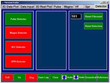
Here you change the detector.
The system will always start in the Pulse mode. If you start without coil and other sensors the detectorboard will look for a coil that need about 30 second and then go to the demomode. Starting with coil need about 15 second. You can also start without coil and the mogno or vlf sensor. The system now need only 5 second.
The detectorboard start directly after power on. If you start the detector software you must first change the detector if you use Magno or Vlf. Select detectors and push the button RESET DETECTOR. Now all detectors are switched off. Now select the detector you will use. You can also change the detector on the fly.
1. Connect the sensor ore the coil..
2. Use the button RESET DETECTORS
3. Wait for the beep. Selct the detector you will use.
4. If the stopped detector is the pulsedetector you can disconnect the coil.
Attention:
If you change to Pulsemode the system will first search the coil. So the Pulsedetector need time to start.
RESET FILECOUNT:
Here you can reset the Logging files on basic value 100. Please note that all other stored files you did before will be overwrite. For example: Pulsdata100.asc or Magnodata100.asc and the following files.
The battery charger consists of following components:
The battery charger is construed for 220V- to 240V AC/ input range. It supplies a constant power of 400 mA to the 21,6 V NIMH-Battery over hole charging time.
Charging time is 15 hours.
Warranty
The warranty time for this instrument is 2 years starting with the day of invoice. During the warranty time our service department will repair every failure of the instrument, which is depending on material or manufacturing. The necessary spare parts will not be charged. Old parts will belong to us.
Exceptions concerning warranty are power and connection cable, rechargeable batteries. Lacks depending on non purpose usage and excluded also. Repairing those failures will be charged. In case of an unfounded warranty claim the demanding person will be charged for all costs. Precondition for fulfilling the warranty duty is the presentation of the invoice. The warranty is not transferable. A service does not extent the warranty time.
Danger
The detector must not be used for mine searching. Special mines react on disturbances
of the earth magnetic field. This mines can be activated by a strong electromagnetic field. Mine fields are marked. Persons with pacemakers or other medical instruments must not use this instrument. The electromagnetic field might influence the rhythm.
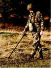
Operating the Detector
The first start should be made with the coil being in the air. So you will learn the behaviour of the detector for a known metal object. The coil is a sensitive receiver and antenna for pulsing signals., which for example are transmitted by monitors, televisions and short wave instruments. So no of this type of instruments should be switched on near the test location. You may eliminate interference signals by turning or tipping up of the coil. There shouldnt be any big metals within a distance of 1,5 2 m (boxes, plates).
Place the coil (28 cm) in a fixed position. You should be able to reach it from all sides with an object. Connect the coil. Please obey that the connector fits right. In case of a loose contact the power amplifier can be destroyed.
Switch the detector on. The detector starts after a few seconds with its factory settings and the operation display. The thermal starting phase begins. A loaded rechargeable battery needs some minutes until it reaches to its actually voltage. Also the electronic gets stabilized. Press the button START RX and after click on REFERENCE from time to time. There must be no metal in the near of the coil otherwise this object will be stored in the compare memory.
Take an object of your choice and move it to the coil. Comes the object in the detection area the graphic display discribed under Detection Display and the loudspeaker are showing a response. Hold this point of detection in memory.
Take the object away und press REFERENCE.
Now repeat this test. You will recognize that the detection depth has increased.
The compare memory has been loaded with current values in air without object. Now bring the object so close to the coil that the tone or the all metal display are near the maximum. Now press the pushbutton REFERENCE again. When you now try the object again you will recognize that you will have to get closer to get a signal. This example shows you what happens when you press the pushbutton REFERENCE during working in the field.
The characteristic of the soil and of the objects are being stored in the REFERENCE memory and only changes of the intensity of signal will be detected. So you need to do the REFERENCE (storing in REFERENCE memory) either in the air, with big distance to the soil or when tilting the coil. Do the REFERENCE always in the air when you want to compensate lowering of the battery voltage or other thermal relating drifting. Otherwise you will loose sensitivity. The REFERENCE should be done step by step. To pinpoint a strong signal move away from the point and go back step by step doing the REFERENCE from time to time. Only the strongest signal will remain.
With the AUDIO up/down you can change the threshold. The value will increase. Click this button until the first click tones can be heart. Up to now this value had to be produced by the object before you could hear a click. This value now is the new threshold. The response is increased now. Test it with your any test object. By the parameter AUDIO you adjust the threshold of the acoustic signal.
Now choose the parameter AUDIO by the pushbutton. Here you multiply the number of clicks by the chosen value. If you have a click rate of 10 clicks per second and your adjusted value is 10 you will get 100 clicks per second. Smallest detection changes can be heart by this feature. For big objects this value should not be too high. By this parameters you are able to double the range of distance compared to the starting parameters. Especially when testing in the air in is recommended to use the REFERENCE after changes of parameters. Because of missing movement of the coil little signal changes do have an influence.
So you should do several tests with different test objects. One of the test objects you can use it a reference object. The preferred test object you should have to always take with you if you work with the detector. You can adjust the ground balance on the area with your test object or take sure that the detector works proper.
By coins or other flat objects you should have to nearing to the detection signal with the coil face or in different coil angles cause the signal strength (Thresh hold) can be different by other position.
With the parameter OBJECT you can fade out the small objects in low depth or the big objects on edge of the detection range. You can compare this with the following procedure.
You detect a coin. You increase the ground range until the signal even lost. A little far a way there are more coins. You will detect by the same ground range the several coins but not the single coin. If you now increase the ground range what you had before over the coins until the signal is still lost you will not detect the coins also even if you are over the coins. A bigger object which is lying in high depth can be ignore by the same procedure.
Big object indicates with a constant signal over a surface. This characteristic can be present by a mineralized ground and that should be fade out on the same procedure.
Note: If you changed the OBJECT value you have to done always REFERENCE.
The DISCRIMINATOR has a range of 1-5. When sensitivity it set to high values it is not possible to detect smallest and big objects in the same way. The discriminator is based on an alloy algorithm. It is comparable to a beam-balance. The possibility for distinguishing is based on the characteristics of the metals. Influential factors are its conductivity, shape, alloy, position and distance.
Furthermore the type of soil is important. The electromagnetic field can be scattered,
directed or bended. Also there is an enormous volume of soil behind the detected object which is detected and measured too. Perhaps here a bigger distance of the coil to the soil or tipping the coil may help.
It is essential that the detecting is reproduce able for a clear identification.
The sum of characteristics of different object may show a silver- or gold-signal depending on position, depth and soil. If you think about how many factors have to
be considered it is not surprising. Therefore test with different objects is necessary.
Bigger or massif precious metals will always show a negative result in the air, if they
are not alloyed. Even clearest gold will be alloyed by crystals and salts in the soil.
In setting 1 the discriminator is most sensitive to filter out iron and massif objects.
A golden ring (333, 485) will be detected clearly. After start the discriminator is set to 1.
Test the different settings with different materials (chains, rings, coins) and observe the reaction of the number-, graphic- and spectrum-display. Mix the materials with iron nails and other materials. By mixing, changing distance and
movement you will learn the reaction of discrimination.
By adding different materials which you move additionally you simulate different
soils e. g. beside lying objects. You should do this with different discriminators and combine it with the described parameters. Often it is also possible to recognize the metal by following the course of detection. Ferromagnetic material produces a long floating course over the complete diameter of the coil. Gold on the other hand produces a lower tone at the edge of the coil.
With the parameter PULSE POWER you change the pulse strength. In air an increase of the pulse power can be recognized only at big objects. The transmission field is not
With the parameter PULSE POWER you change the pulse strength. In air an increase of the pulse power can be recognized only at big objects. The transmission field is not
disturbed through its way through the air and is very stable for that reason. The field can close very early. Small object causes only small disturbances for that reason.
With increasing power in the air the sensitivity for small objects decreases. Depending on the soil this effect will be seen up to about 50 cm too. This applies to the high current detectors Nexus and Genesis.
So it is always recommended to use the possibilities of the parameters GAIN INCREAMENT before increasing the pulse power.
Test the change of increasing the power with your testing objects. Test on which object size by increasing the power you have no more depth. Increasing the power means to use more battery capacity. You can estimate vaguely up which object size as a single object is not be recognize. Certainly that value to the local ground conditions. He it can help only the praxis.
During your detecting you have a constant tone level and when suddenly the tone level increase over an bright place so you find your self perhaps on a highly mineralized surface.
Decrease the sensitivity with the GAIN DECREMENT until you have a constant signal level. If the signal gets lower you can increase the sensitivity with GAIN INCREMENT again.
If you want to hold the detecting depth you should choose over FREQUENCY the low pulse frequence. With this you have better penetrating of mineralized ground.
The physical features of the frame coils has to be note absolutely. The primary- and secondary field of the frames are equal to an AC. The folded coil build a transformer. The each segments inducts to each other an electrical current. Depending on the folding this
electrical current is opposite to the normal current direction and this will come to a inducted short-circuit. That will come to a high current consumption which will come up to quadruplicate of current.
Depending on the power of the parameters and adjustments the detector can be destroyed. So always stretched out the coil before you start the detector.
If you use a frame coil you should increase the OBJECT value always. You will note if you have a permanent tone signal over the ground. Otherwise You will not reach high depth.
Operating MagnoRadarCoil

With the MagnoRadarCoil you can detect the disturbance or anomalies in the earth magnetic field. This anomalies caused by the ferromagnetic (iron) objects or mineralized structures, cavities, graves, faults, shafts, groundfills, deposits etc.
The MagnoRadarCoil has 8 sensors with 2 axis. It can detect a irregularity of earth magnetic field of 10nTesla.
The coil is able to detect the magnetic field irregularity of a 10 x 3 cm nail.
The archaeological founds in the ground contains always a high part of ferro magnetic materials.
That is caused also by coins. There are never content from clear precious metals. Normally the environment or the packaging is ferromagnetic afflicted.
The detection signal and the difference display handle the left and right side of the coil. One object which makes a disturbance on one side that means immediately a detection signal. If there is no disturbance so the both side is balanced. So with this difference detection you can make a real-time detection.
The indicated values of each sensors are given by numeric and by spectrum. The indicated values of the sensors will be calculated in a function to a minimum-middle- and maximum value. This value will be shown on the plot in coded colour. You will get with this a disturbance of field structure.
Note:
By measuring you have to hold always one direction. If you want to change the direction you have to stop the plot with the button STOP and change the direction than make a REFERENCE and than start again the recording with the button GO. That necessary because the direction of the magnetic field changes always in a positive signal. If you are in an area where you have strong disturbance by each moving the coil than you can reduce the sensitivity with the RESOLUTION. Otherwise you have no discrimination on the detection graphic. You always measure the difference to the latest point where you have done the REFERENCE.
Operating Vlf Radar
The sensor is a passive differential longwave receiver.
The sensor is a closed processing system. The transmitting waves of the longwave transmitter
cd penetration. It is possible to select anomaly of the conduction in the ground.
The sensor compare the air and ground wave.
Depending on the frequency and performance of the transmitter are hollow and all metal structures can be seen.
The probe is vertically oriented. The search range is very small and allows targeted.
In Europe there are countless long wave transmitter for this positioning. This positioning is optimal for metal and cavity detection.
But even here, there is no information of deep possible. The advanced probe has not yet in addition, a 3 axis magnetometer. So, you can simultaneously the disruption of the magnetic.
The probe must always perpendicular to the ground. They are often by land structure (rock, etc. ) the signal disturbed and measure more difficult.
It is found that a long wave transmitter in the development of defined frequency and performance even more precise allowed. Thus, the system will work on every country
send us your inquire, we will sent you all
informations, also user manual how work it mail to:
info@bravodog.com
o admin@wilsonelectronics.info Geophysical Exploration
Systems
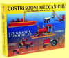
GEORADAR system
12
There Georadar system 12, portable, of new
generation and elevated technology, centers it them radar e' the directly
interfacciata to notebook pentium with display to colors, in order to see what
e' in sottosuolo and relative stratografia to colors. Georadar system the 12 e'
indispensable for taken care of continuous and not destructive surveyings and
superficial visions and of the sottosuolo. For the searches they are not demands
diggings, not you e' risk to interrupt lines or pipages and are not necessary
cables to spread; only an antenna to pass on the land. The indispensable
Georadar e' for multiple applications: localization and optimization of
archaeological diggings, survey of I placed and buried objects, mines and
tunnel, controls of street paving, profiles of the sottosuolo, search of
stratums, fractures to you and cavita', glaciologia, survey pipages and cables
and areas sottosuolo contaminated. Used also in civil engineering for searches
of smottamenti and control of bridges, palaces and constructions in c.a.,
diggings prefoundations, ect
Technical characteristics: data visualize to
you in real Time on the display of the PC, Time range from 50 to 2000 nanosec,
transmit range: 115 KHz, adjustable gain, filters: verticall/horizontal low and
higt-pass filter, matched filter, inverse filter, migration filter, envelope
filter, median filter, ect. transfer given via rs-232C, feeding 12V Dc,
consumption 0,7 Ampere. Weight 3Kg. Elevated precision and resolution from first
cm. until 30 mt. of the sottosuolo with the aid of the following antennas:
unita' 2000 Mhz dimensions 27x13x13 cm and 1,5
weight Kg, of maximum precision until 2mt, unita' 900 MHz dimensions 43x22x2,
weight 2 kg, for profondita' until 5 mt. unita' to 500 MHz dim. 69x32x3 and
weight 4 kg for prospectings until 10mt, unita' 300 MHz dim. 98x52x4, weight 10
kg for prospectings until 15 mt, unita' to dipole in air from 150 MHz fine
weight 6 kg for prospectings until 30 mt. The equipment radar composed standard
e' gives: it centers them operating radar, notebook with the special software
and operating handbook of management in English language, probe from 2000
interchanging MHz, battery and cables of connection.
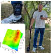
Example of prospecting of three tubes buried in
the sottosuolo to one profondita' of approximately 1,2 mt. Every tube generates
marks having them the hyperbolic shape, to which appendix corresponds the exact
lease of the tube. The survey e' be executed with the antenna of sensibilita'
from 2000 MHz. And prospecting of ghiacciai. It encloses you to the equipment
radar are added to photo examples prospectings and surveys accompanied from
explanations. The equipment radars and relati software to you is always in
continuous development, for further information not hesitated to contact to us.
EURO 15400 while for the chartering e' available to 775 for 15 days.